Industrial Steel-Framed Building & 3D Portal Frame
An industrial steel-framed building documented through column setout, roof framing, braced elevations, connection details, and a 3D portal frame model - the kind of drafting industrial fabricators and engineers rely on.
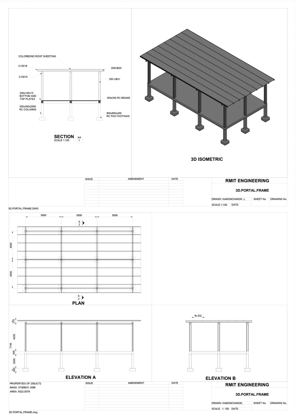
- - Column setout plan
- - Roof framing plan
- - North and south steel elevations
- - Steel sections (apex and cross)
- - Column cap and base details
- - Wall brace, roof bracing, and flybrace details
- - 3D isometric portal frame
About the project
An industrial steel-framed building exercise covering the structural drafting industrial sheds, factory units, and small warehouses typically require. The drawings demonstrate steel structure documentation conventions used across Australian fabrication and engineering practices.
Drawings produced
Column setout plan
Column grid at 4800 mm × 5500 mm typical spacing, with column markers C1A through C3D laid out on a three-bay-by-two-bay plan. Includes intersection coordinates, slab reference (refer drawing GS1), and mullion markers (M1) for door framing.
Roof framing plan
Eaves beams (EB1–EB6) and floor beams (FB) coordinated with the column grid. Purlin run-back roof bracing (PRB1–PRB4) at the corners. Box gutters at both eaves with roof sheeting and eaves purlin annotations.
North and south elevations
Steel portal frame elevations showing eaves beam connections (EB1–EB6), prop bracing (PRB), wind bracing webs (wb1, wb2), and rafter geometry. The south elevation integrates a 2700 W × 2400 H roller door with mullion and door head framing (DH1).
Drafting conventions
Standard 1:50 and 1:75 scales, AS-compliant grid annotation, member-mark conventions matching industrial fabrication shop drawing practice. Bracing webs explicitly marked with wb1/wb2 notation tied back to the column setout.
What this demonstrates
Industrial steel-frame drafting fluency - the structural members, bracing, framing, and fabrication-ready notation that industrial buildings require.