Reinforced Concrete Structural Details
Reinforced concrete column and footing details, beam reinforcement schedules, structural footing plans, and reinforcement drawings produced to typical Australian engineering practice conventions.
- - Column detail drawings at beam and slab
- - Pad footing detail drawings
- - Beam reinforcement schedules
- - Column section and elevation drawings
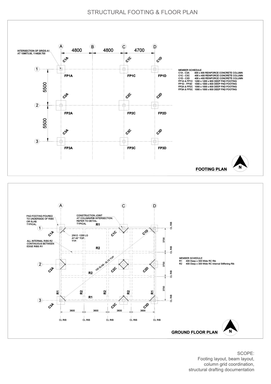
- - Structural footing and floor plans
About the project
A structural detailing exercise covering the technical drawings a typical Australian structural engineering practice produces day-to-day. The work demonstrates fluency in concrete reinforcement representation, column and footing detailing, and beam schedule drafting.
Drawings produced
Column detail at beam or slab
Standard column detail showing reinforcement crank bars (1 in 6 max), tie sets at crank locations, construction joint placement, and references to the column schedule for sizes and reinforcement.
Typical pad footing detail
Pad footing detail including starter bar lap (matched to column bar count), tie sets, 50 mm blinding concrete, standard chair detailing, scabble surface preparation, and footing schedule references.
Beam reinforcement schedules
Ground floor plan beam reinforcement detailing - 3-N20, 3-N24, 3-N28 bar arrangements with 9@100 mm stirrup spacing at supports transitioning to 4@200 and @300 mm at mid-span. Two-leg N12 stirrups throughout 400×250 mm beams. Section markers tied to detail sections (1B5, 1B6).
Drafting standards
All drawings use 1:25 and 1:100 standard scales, AS-compliant titleblock format, and proper notation of overbreak fill, footing schedule cross-references, and tie configuration. Drawing notes follow the conventions structural engineers expect on detail sheets.
What this demonstrates
The structural drafting fluency real engineering practices need - reinforcement schedules, footing details, and the kind of tight drafting that makes detail sheets actually buildable.