Urban Residential Subdivision - Civil Engineering CAD
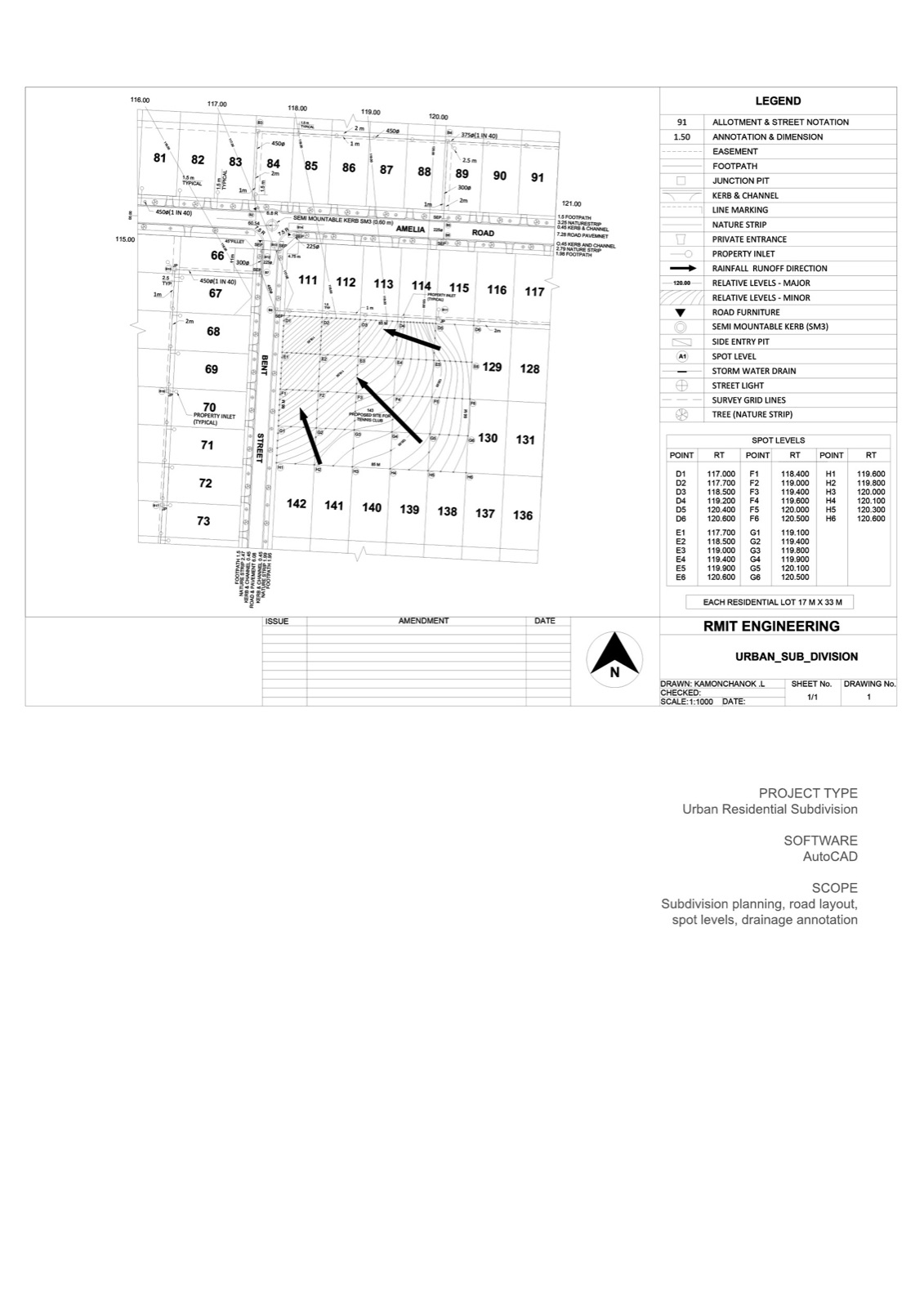
An urban residential subdivision plan drafted in AutoCAD - road geometry, stormwater drainage, spot levels, and allotment layout at 1:1000 scale.
- - Subdivision planning and road layout
- - Allotment numbering and dimensioning
- - Spot levels and contour grading
- - Stormwater drainage layout
- - Kerb, channel, and footpath detailing
- - Property inlets and junction pits
About the project
A residential subdivision drafting exercise from RMIT’s civil engineering programme. The brief covered subdivision layout, drainage planning, and the technical drafting standards Australian civil engineering practices use day-to-day.
What the drawing covers
- Allotment layout: Numbered residential lots at 17 m × 33 m typical, arrayed along Amelia Road and Bent Street
- Road geometry: 7.28 m road pavement, 1.5 m footpath, 3.25 m nature strip, 0.45 m kerb and channel
- Drainage: Stormwater drains, junction pits, side entry pits, property inlets, semi-mountable kerb (SM3)
- Levels: Major relative levels every metre, minor levels at 0.5 m, spot levels at D, E, F, G, H survey points
- Other: Street lighting, tree positions in nature strips, line marking, road furniture, easements, footpaths
Drafting standards
The drawing uses a standard 1:1000 scale, full survey grid lines, AS-compliant line types and symbology, and a complete legend documenting every annotation type used. Drafted to RMIT Engineering standards which mirror Australian civil engineering office conventions.
What this demonstrates
The civil drafting discipline that supports infrastructure and subdivision projects - drainage layout, level annotation, and the dense technical drawing conventions Australian civil engineering practices expect.